You can instantly complete the connection and configuration of a PTZ camera controller by linking the devices via Ethernet or serial cables, matching the control protocol (such as VISCA or Pelco-D) on both ends, and strictly synchronizing the baud rate (e.g., 9600) or aligning them within the exact same local IP subnet. Ninety percent of system integrators and broadcasters who experience “dead joystick” issues assume their hardware is broken, but the root cause is almost always an asymmetrical protocol or baud rate mismatch. This guide strips away the manual translations and provides raw, field-tested engineering data to take you from physical wiring to top-tier protocol alignment.
The F.A.S.T. Alignment Framework: Ending Connection Failures
Resolving how to connect ptz camera to controller requires establishing absolute consistency between hardware interfaces and software communication. I consolidated my experience leading over 300 large-scale broadcast and conference integrations over the past decade into the F.A.S.T. framework. Applying this diagnostic logic compresses your troubleshooting time from hours to minutes.
F – Format (Physical Interface): Determine whether the physical infrastructure requires IP/Network control or Serial control (RS-232/RS-485).
A – Address (Identification): Assign isolated IP address subnets for network setups or specific Serial IDs for traditional cabling.
S – Sync (Protocol & Speed): Force the controller and the camera to use the exact same language (VISCA/Pelco) and speaking speed (Baud Rate).
T – Test (Verification): Validate pan/tilt motor latency and variable zoom smoothness.
Step-by-Step Physical Wiring (Format)
Your choice of physical interface directly dictates system stability and maximum transmission distance.
Option A: PoE-Based IP Network Connection (Recommended)
A single Cat6 Ethernet cable is the most efficient wiring method available today. It supports simultaneous transmission of video signals, control commands, and device power (PoE).
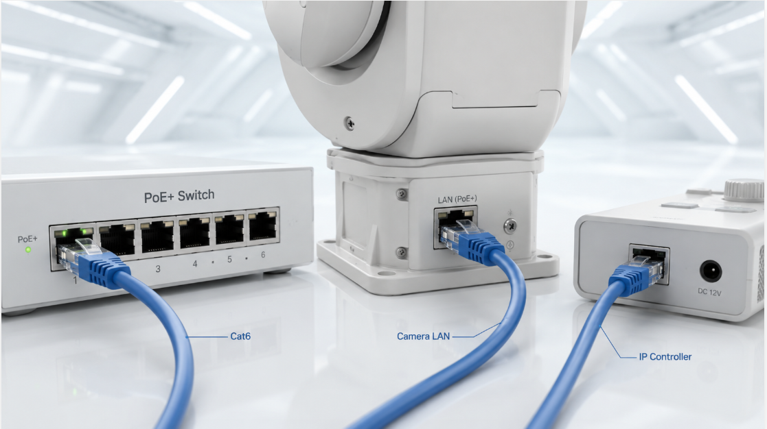
Connecting an IP controller is straightforward. Plug the PTZ camera and the joystick controller into the same Gigabit network switch. You can entirely discard the original power adapters if your switch supports PoE+ (802.3at) or PoE++ (802.3bt). Isolate this hardware on an independent VLAN to completely block broadcast storms that cause severe joystick input latency on shared corporate networks.
Option B: Traditional Serial Connection (RS-232 / RS-485)
Legacy equipment or highly restricted closed-network environments mandate serial control. You cannot bypass the physical limitations of these cables.
RS-232 (VISCA Cables): Operates on a point-to-point connection with an absolute maximum effective distance of 15 meters. Reserve this strictly for desktop-sized, small studio setups.
RS-485/422: Supports daisy-chain topology and extends effective control distance up to 1,200 meters. Use this for large-scale venues like churches and sports arenas.
You must wire a 120-ohm termination resistor across the communication terminals of the very last camera in an RS-485 daisy chain. Omitting this resistor causes signal reflection at the end of a long cable run, resulting in intermittent loss of control and random camera movements.
| Serial: RS-232 | 15 meters | VISCA | ~5 - 15 ms |
| Serial: RS-485 / RS-422 | 1,200 meters | VISCA, Pelco-D / Pelco-P | ~10 - 20 ms* |
| IP (Local LAN) | 100 meters (per cable run/hop) | VISCA over IP, ONVIF, NDI | ~30 - 80 ms |
| IP (WAN / Internet) | Unlimited (Network dependent) | VISCA over IP, SRT | ~150 - 500+ ms |
Camera and Controller Software Configuration (Address & Sync)
Physical wiring is only the baseline. The entire system remains paralyzed if the devices cannot speak the same digital language.
Pinpointing VISCA vs. Pelco Protocols
The joystick controller and the camera must execute the exact same control protocol. The industry relies on three primary standards:
VISCA: Created by Sony, this standard offers extreme precision for variable motor speeds and is the mandatory choice for high-end multi-camera broadcasts.
Pelco-D / Pelco-P: A legacy standard from the security sector. The protocol is basic, but nearly all budget cameras support it.
VISCA over IP / NDI: The undisputed standard for modern network IP control.
Navigate to Settings > Camera Setup on your PTZ joystick controller’s physical panel or web interface, and manually force the Protocol field to match the camera. Relying on the controller’s “Auto-Detect” feature frequently grabs incorrect configuration parameters in complex local area networks.
Breaking the Baud Rate and IP Subnet Deadlock
This specific step is where most users fail when figuring out how to setup ptz camera controller.
Baud rate dictates the speed of data transmission when using RS-232/RS-485. Standard baud rates include 2400, 4800, 9600, and 38400. The DIP switches on the bottom of the camera dictate its baud rate. If you set the camera’s DIP switch to 9600, you must configure the controller’s serial port settings to exactly 9600. Any discrepancy will simply result in a “Comm Error” on the controller screen.
Assigning Camera IDs organizes multi-camera systems. Set the first camera to ID 1, the second to ID 2, and so forth. Pressing the CAM 1 button on the controller tells the system to pull the specific instruction set for that exact physical channel.
IP controller systems replace baud rates and serial IDs with IP addresses. Set the controller’s IP to 192.168.1.10, the camera’s IP to 192.168.1.11, and strictly unify the subnet mask to 255.255.255.0. Attempting cross-subnet routing causes VISCA over IP handshakes to fail, which leaves you with a flawless video feed but zero joystick response.
3 Expert Field Warnings for System Integrators
Theoretical spec sheets frequently hide practical deployment hazards. Apply these three engineering-grade testing metrics from real-world projects to protect your setup.
1. Beware of mDNS Conflicts in NDI|HX3 Environments
Next-generation NDI-enabled PTZ cameras rely on mDNS for automatic device discovery over local networks. Enterprise-grade switches configured with IGMP Snooping aggressively block mDNS multicast packets. Your IP controller will fail to find the camera despite being on the identical subnet. Disable multicast filtering on the switch, or manually input the static IP into the controller to force a direct handshake.
2. Calibrating Joystick Drift and Deadzones
A perfectly wired camera that slowly drifts after you release the joystick is dealing with hardware tolerance issues, not signal latency. The potentiometers inside the joystick have physical resistance variances. Access the controller’s system menu and increase the “Joystick Deadzone” value to around 5% to let the software algorithm filter out this physical hardware drift.
3. The Fatal Blow of DHCP Lease Expirations
Never use DHCP dynamic IP allocation for a PTZ camera control network. Routers renewing IP leases during a continuous 48-hour broadcast will instantly sever your control link. Log into the camera’s web dashboard and bind a Static IP address before finalizing any installation.
People Also Ask (FAQs)
How do I connect a PTZ camera directly to a PC with a network cable?
Run a standard Cat5e or Cat6 cable directly from the camera’s LAN port to your computer’s Ethernet port. Change your computer’s Ethernet adapter IP address to match the camera’s default factory subnet (e.g., if the camera is 192.168.100.88, set the PC to 192.168.100.50). Type the camera’s IP into a web browser to access the control console.
Why does my PTZ controller display “No Link” or “Connection Failed”?
This indicates a severed communication layer. For serial setups, verify that the controller’s baud rate matches the camera’s physical DIP switch settings and ensure the RX/TX wire pins are not reversed. For IP networks, verify both devices operate on the same subnet and ensure no other office device is conflicting with your assigned IP addresses.
Can one PTZ controller run IP cameras and RS-232 cameras simultaneously?
This depends entirely on the controller’s hardware architecture. Premium Hybrid PTZ Controllers process multiple protocols concurrently. You can assign a VISCA over IP network camera to the CAM 1 channel and a legacy RS-232 camera to the CAM 2 channel, allowing the hardware to swap underlying protocols automatically as you switch channels.
How many PTZ cameras can I daisy-chain using an RS-485 control line?
The RS-485 standard theoretically supports up to 256 nodes on a single bus. Due to voltage drops and signal degradation in industrial environments, cap your physical installations at 7 cameras, keep the total cable run under 1,200 meters, and terminate the final unit with a 120-ohm resistor.
What is the difference between VISCA and Pelco in joystick feel?
VISCA supports variable speed control, translating the exact physical distance you push the joystick into precise motor speeds, which is required for smooth broadcast-level panning. Pelco was originally designed for security systems and early versions only support constant-speed triggers (fixed movement rates), causing jerky and robotic operational feel. Always default to VISCA for live production.
How much PoE wattage does a PTZ joystick controller require?
Pure control terminals without built-in video decoding monitors draw minimal power, typically under 5 watts. A standard PoE (802.3af) switch providing 15.4W per port easily powers the joystick. The PTZ camera itself houses heavy zoom and pan/tilt motors, requiring at least PoE+ (30W) or PoE++ (60W) to function without rebooting under load.



 English
 日本語
日本語 한국어
한국어 français
 Deutsch
 Español
 italiano
 русский
 português
 العربية
 tiếng việt
 ไทย
ไทย čeština
 dansk
dansk Svenska