Maximizing Pan&Tilt efficiency requires rigorous synergy between dynamic load matching, absolute value encoder accuracy, and low-latency communication protocols. Integrators and OEMs who build pan & tilt systems for critical infrastructure must never make decisions based solely on basic static parameters. The real test of a heavy-duty pan and tilt system is whether it can maintain a return-free tracking accuracy of 0.01° in coastal winds of 120 km/h and when dealing with asymmetric multi-sensor loads. This engineering guide will skip the basic definitions and go straight to the core machinery, protocols, and integration framework that determine whether a system can survive in maritime, border defense, and industrial applications.
LAI Of Current Pan&Tilt Efficiency Three-Tier Architecture
To develop a reliable pan and tilt system, we must establish structured thinking in mechanical and data processing. LAI The architecture provides a specific set of mathematical and logical models to effectively prevent premature motor wear and tracking drift.
Layer 1: Load Mechanics
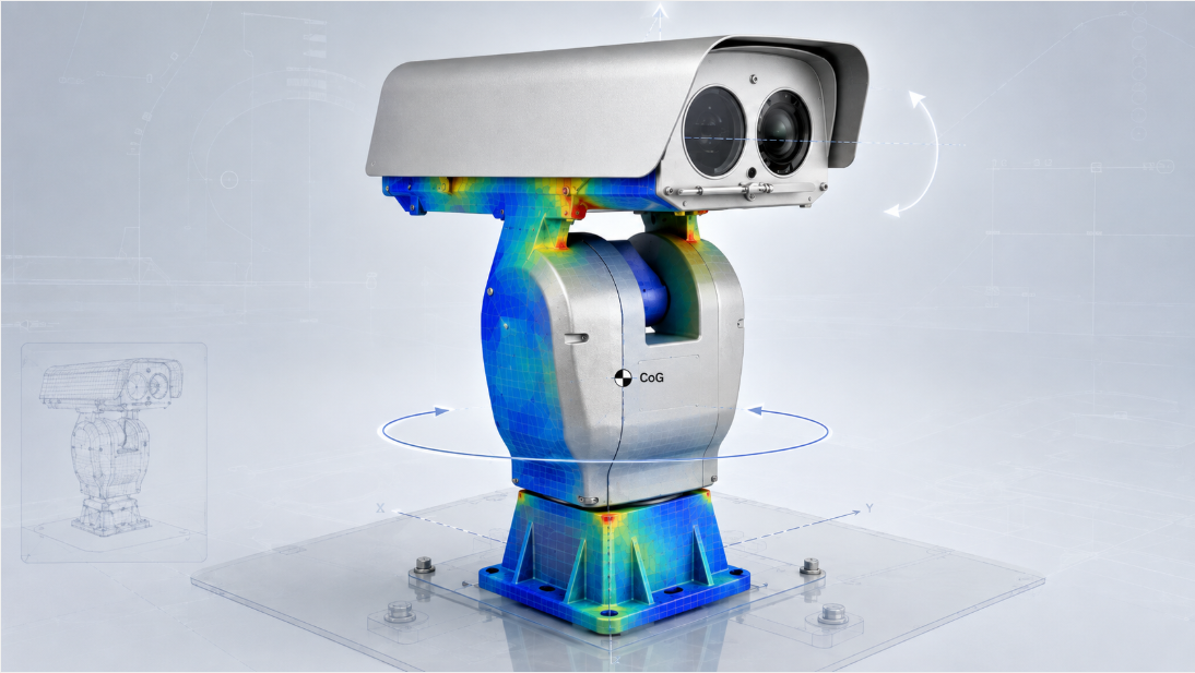
Errors in load calculation are the main culprits for premature mechanical failure of heavy-duty gimbals. When engineers choose a pan and tilt system, they often only look at the static weight of the camera housing. However, a 30kg set of thermal imaging and visible light dual-bin equipment has a center of gravity that deviates from the center of rotation by a different distance, and the torque generated on the pitch axis will be completely different. This asymmetric weight distribution multiplies the dynamic load when mounting a multi-sensor combination e.g., combining a long-range laser night vision device with a heavy thermal imaging lens. Therefore, the evaluation system must look at torque capacity rather than the mere static indicator of kilograms.
Layer 2: Absolute Positioning
Long-range monitoring systems must rely on absolute value encoders to maintain target lock at ultra-teleoptic ranges. Incremental encoders lose their physical reference points once they lose power or experience severe mechanical shock, and have to go through a complete self-test homing procedure to find the “zero point”. Absolute angular feedback is different, assigning a unique digital signature to every degree of precision in level and pitch. If a pan&tilt locator is aiming at a laser target 10 km away, even with a mechanical drift of only degree, the deviation will exceed 170 meters. Absolute control ensures that the radar linkage system instantly jumps to the precise coordinates provided by the radar without excessive overshoot or dragging of mud or water.
Layer 3: Integration Protocol
Delays in the communication bus can directly reduce the efficiency of the automatic tracking system. Conventional closed-circuit television deployments typically rely on the 9600 baud rate, RS485-based Pelco D/P protocol, which is more than adequate for manual joystick operation. However, in automatic border and coastal defense scenarios, the system requires high-frequency and continuous coordinate polling. To feed radar coordinates to the pan and tilt system in real time, the polling rate must be adjusted and an optimized RS422 or IP-based instruction structure must be used to minimize the microsecond delay between radar detection and motor mechanical response.
Direct Drive Servo And Worm Gear: Transmission Mechanism Selection Logic
Choosing between a direct drive servo motor and a worm gear directly determines the life or death of pan&tilt equipment in strong wind environments. Worm gear drive has excellent self-locking ability when resisting heavy external impact. When power outages occur, or sudden coastal winds sweep around the massive dual-cabin camera housing, the mechanical nature of the worm gear prevents the winds from forcibly twisting the rotating shaft. In contrast, direct-drive servo motors have the advantage of completely eliminating mechanical backset and rotating extremely fast; however, they require a continuous input current to maintain the holding torque (Holding Torque), which means that in the face of wind resistance, direct-drive systems can only rely on software and electrical energy to harden the resistance, rather than relying on passive mechanical self-locking.
| Feature | Worm/Gear Drive Pan&Tilt | Direct Drive Servo Pan&Tilt |
| Backlash | Minimal (requires tight machining) | Zero (Direct motor coupling) |
| Holding Torque | Excellent (Passive self-locking) | Moderate (Requires active power) |
| Speed Range | Low to Medium (Typically <60°/s) | Very High (Often >100°/s) |
| Ideal Application | Marine/Harbor, Heavy Top Loads (60kg – 120kg) | Antenna/Radar Rotators, High-Speed Tracking |
| Power Failure State | Holds physical position mechanically | Loses position, axis may swing freely |
Exclusive Port Wind Load Test Data
In an environmental test simulating wind speeds of 100 km/h, we pitted a BIT-CCTV 60kg load-bearing gimbal against a standard servo-driven commercial gimbal, revealing a clear efficiency gap. The servo-driven device, in order to maintain azimuth in wind resistance, saw a 400% spike in continuous power consumption and triggered a thermal overload protection shutdown after 45 minutes of hard resistance. The worm gear system maintains absolute physical locking with near-zero holding power consumption, leaving all current losses purely to active displacement commands.
Top 3 Engineering Pit Avoidance Guides For Heavy-Duty Pan&Tilt Deployments
The reason why on-site deployments often fail is often because system integrators use industrial-grade positioning gimbals as consumer-grade camera gimbals. Avoiding the following specific mechanical and environmental pitfalls is the key to keeping your project running long-term and away from endless after-sales maintenance.
Trap 1: Ignoring The Center-Of-Gravity Offset Of The Multi-Cabin Shell
Mounting a heavy lens too high off the pitch axis creates a noticeable “pendulum effect”. Integrators often don’t do the counterweight balancing for the mounting plate when assembling customized top loads. This imbalance causes the pitch motor to have to fight gravity when pitching up and fight inertia when braking down. Reducing the load center of gravity as close to the center of the rotating shaft as possible and using raised spacers only when absolutely necessary can significantly reduce motor wear and prevent gear sweeping.
Trap 2: “Windage Area” Blind Spot In Coastal And Border Defense Projects
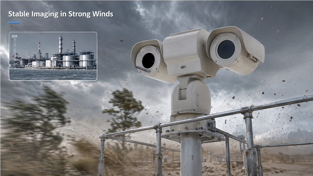
In an open outdoor environment, surface area is much more lethal to system stability than actual mass. A lightweight but bulky shield will create “sail effect” to catch the strong wind. A pan and tilt system rated at 30kg can be easily carried with a compact 30kg lead block in the laboratory; but if a lightweight housing weighing 15kg but with a huge windward side is mounted in a maritime environment, a storm can easily overload the motor’s operating torque. During the initial specification phase, wind resistance mechanics must be included.
Trap 3: Protocol Polling Rate Bottleneck In Radar Tracking
Bombing the RS485 bus with uninterrupted status query instructions will cause visible stuttering in the video picture. Many multi-sensor tracking software will frantically send instructions to the pan&tilt gimbal for absolute angle feedback. Sending these massive requests on a serial connection with a low baud rate will inevitably cause command package conflicts. Optimizing the control software, setting it to request angle feedback only at specific intervals, or directly upgrading the RS422/RS232 connection using a higher bandwidth can ensure that the motion vector commands received by the motor are unobstructed.
The high efficiency of industrial-grade pan&tilt relies on seamless mechanical collaboration between differentiated sensing technologies. A telephoto HD network visible light camera and a cooled/uncooled thermal imaging unit may be integrated simultaneously within a single shield. At this time, the gimbal must have the speed change control capability that can be linked with the variable rate. At 1x wide-angle view, the 10-degree-per-second horizontal rotation is smooth and seamless; but at the same speed, at 60x optical zoom, the picture becomes a chaotic and unwatchable afterimage.
Deploy a system with absolute control and angle feedback, and the integrated software calculates the exact “speed-zoom ratio”. BIT-CCTV has manufactured customized light, medium and heavy duty positioners specifically to cope with this complex multi-sensor load. By employing an absolute value encoder and a custom worm gear or servo drive configuration, the mechanical system is able to respond with accurate and highly repeatable accuracy when the border defense system issues a fine-tuning instruction of 0.05° to identify heat source features 5 km away.
FAQ
How to calculate dynamic wind load of pan and tilt system?
When calculating wind load, engineers first measure the total frontal windward area of the camera housing and the bracket, substitute the expected maximum wind speed, and then convert the calculated wind resistance into the rotational torque (Newton-meter) acting on the horizontal and pitch axes.
How is mechanical backset generated in heavy-duty pan&tilt positioners?
Backset refers to the tiny physical play or “wobble” between gears inside a drivetrain. This phenomenon occurs when the gear teeth do not bite perfectly, usually caused by manufacturing tolerances in high-pressure environments or long-term mechanical wear.
How does absolute angle feedback improve the efficiency of radar linkage tracking?
Absolute angle feedback provides accurate physical orientation of the pan&tilt gimbal 24/7. When the radar detects a moving target, the system instantly calculates the exact mathematical difference between the current absolute angle and the target coordinates, completely eliminating the steps of traditional equipment to go back and forth “search” or recalibrate.
In pan and tilt system, what is the difference between direct drive motor and worm gear transmission?
Direct drive servo systems, which directly couple the motor to the shaft, have zero return and extreme speed response, but must be continuously energized to lock the position. The worm gear adopts a threaded transmission mechanism to provide passive mechanical self-locking ability, which can prevent the gimbal from being forcibly twisted by external forces such as strong winds even in a power-off state.
How does multi-sensor loading affect the motor torque demand of pan&tilt?
Putting different sensors together tends to pull the physical center of gravity away from the absolute center of the pitch axis. This offset creates an asymmetric mechanical lever that forces the motor to output much greater torque to complete rotation and braking.
Which communication protocol minimizes latency in pan and tilt systems?
While RS485 with Pelco D/P is industry standard for regular control, full-duplex RS422 or direct IP-based control protocols can minimize latency. They allow the system to synchronously transmit back absolute position data while receiving motion instructions, never causing packet collisions.
How can the pan&tilt system maintain stability on maritime vessels?
The maritime environment requires a gyroscopic stabilization system built into the control board. The device uses high-frequency IMU sensors to accurately capture the undulations of ocean waves and instantly drive horizontal and pitch motors to compensate for the motion in completely opposite directions, thereby offsetting physical displacement.
Can a standard pan and tilt system carry both thermal imaging and laser night vision devices?
Standard commercial gimbals fall short of both the upper load limit and the physical installation space. Industrial-grade dual-cabin or heavy-duty top-loading pan&tilt equipment has enhanced structural rigidity and output torque from the beginning of its design. It is designed to carry thermal imaging and laser equipment at the same time and can ensure that the central axis never drifts.



 English
 日本語
日本語 한국어
한국어 français
 Deutsch
 Español
 italiano
 русский
 português
 العربية
 tiếng việt
 ไทย
ไทย čeština
 dansk
dansk Svenska